Use Path Outages to Suppress Notifications
An outage on a central network component can cause a large number of node outages.
You can use path outages to suppress notifications based on how nodes depend on each other in the network, as outlined in a critical path definition.
The critical path must be configured from the network perspective of the monitoring system.
By default, the path outage feature is disabled and must be enabled in poller-configuration.xml.
Enable path outages
By default, the path outage feature is disabled and has to be enabled for pollerd to check if notifications should be suppresed for an outage.
Edit the ${OPENNMS_HOME}/etc/poller-configuration.xml file to set pathOutageEnabled to true at the top of the file.
A service restart is required after changing this setting.
Example: Configure parent nodes
Path Outages can be used to suppress notifications generated by notifd for uei.opennms.org/nodes/nodeDown events.
It will not suppress the creation of uei.opennms.org/nodes/nodeDown events or associated alarms.
|
The following image shows a sample network topology:
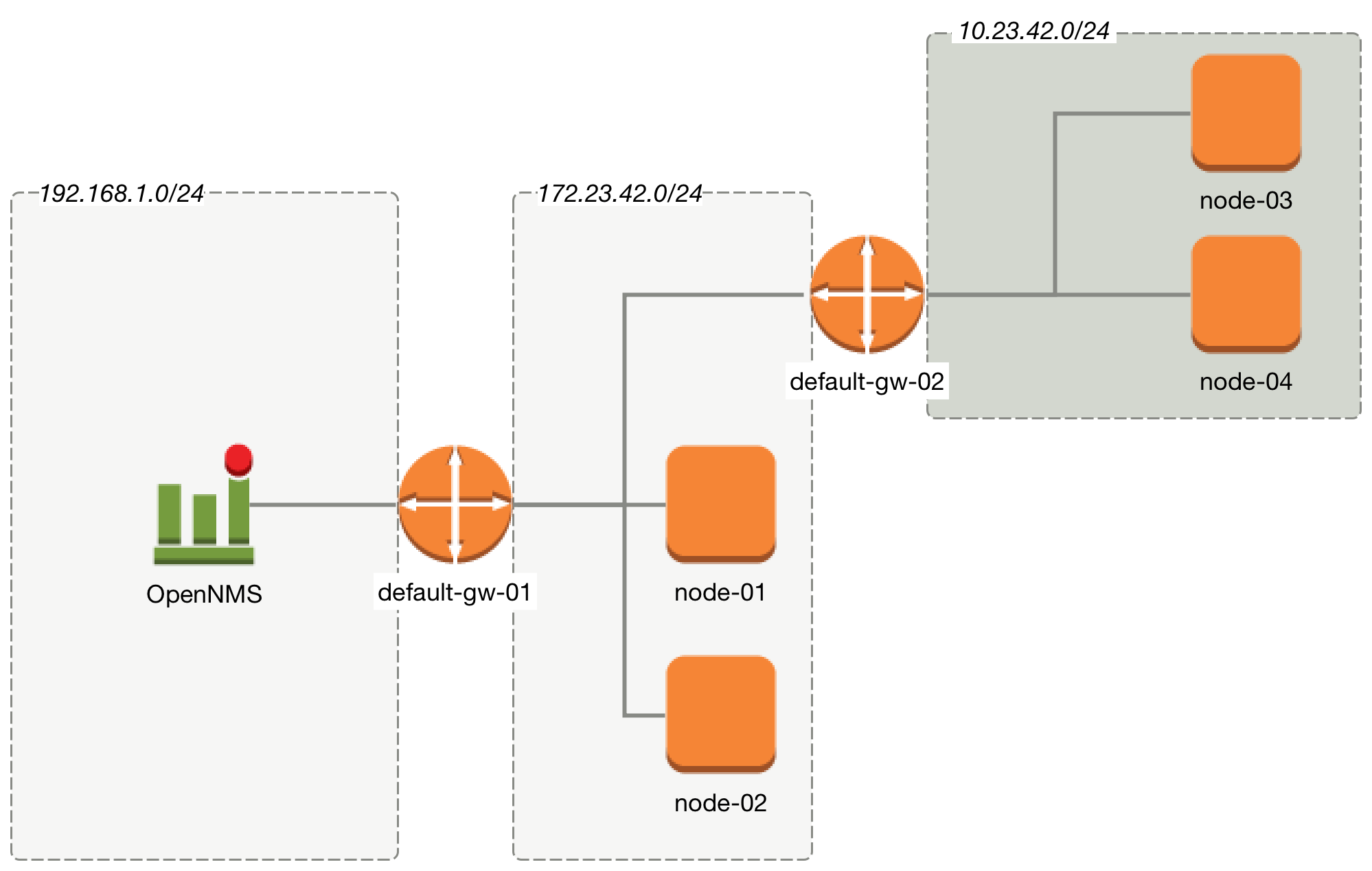
From the perspective of the monitoring system, a router named default-gw-01 is on the critical path to reach two networks.
If default-gw-01 is down, it is not possible to reach any node in the two networks behind it.
In this case, an administrator should receive only one notification for default-gw-01; notifications for the other nodes behind it should not be generated.
Building this configuration in Meridian requires the following information:
- Parent Foreign Source
-
The foreign source where the parent node is defined. If the parent node is in the same requisition as the child node, this field can be left blank.
- Parent Foreign ID
-
The foreign ID of the parent node this node depends on. It is possible to define the parent node based on the label, though using the ID is more reliable in case the node label changes in the future.
- IP Interface
-
The primary IP interface is used as the critical IP. While you do not need to provide the IP interface when configuring the path on the node in a requisition, it is important to make sure the node has the correct IP interface set as the primary for the path calculation.
In this example, we have created all nodes in a requisition named Network-ACME and we use the node label value as the foreign ID:
-
Click the gear symbol in the top-right of the screen.
-
Under Provisioning, click Manage Provisioning Requisitions.
-
Click Edit beside the requisition that you want to modify.
-
Click Edit beside the node that you want to modify.
-
Navigate to the Path Outage tab, and configure the network path using the following parameters:
Parent Foreign Source Parent Foreign ID Provisioned Node Not defined
Not defined
default-gw-01
Network-ACME
default-gw-01
node-01
Network-ACME
default-gw-01
node-02
Network-ACME
default-gw-01
default-gw02
Network-ACME
default-gw-02
node-03
Network-ACME
default-gw-02
node-04
The primary IP interface is selected as the critical IP.
In this example, it is important that the IP interface on default-gw-01 in the network 192.168.1.0/24 is set as the primary interface.
The IP interface in the network 172.23.42.0/24 on default-gw-02 is also set as a primary interface.
|