Asset Topology Provider
Meridian lets users define arbitrarily complex layered topologies using GraphML. Refer to the GraphML section of the Meridian developers guide for details of how Meridian interprets GraphML. The ability to display complex layered topologies is a great feature, but creating a usable GraphML topology for a large network can be a complex task.
The Asset Topology Provider avoids the need for users to work directly with GraphML, by directly generating a layered GraphML topology based on node parameters and the contents of the node asset table. The Asset Topology Provider simplifies the task for many use cases by allowing users to define fields in the node asset table, which lets you position nodes correctly in a complex topology. This lets you order nodes physically and logically, which makes it easier to represent and navigate your infrastructure.
The structure of the generated topology is determined by the assetLayers configuration constant that users can set.
To illustrate how this works, consider the following configuration:
assetLayers=asset-region,asset-buildingThe Meridian asset table is parsed to generate nested layers in the order of the comma-separated keys in the assetLayers property. Each layer is a graph named after the key. Graph nodes in each layer reference related graph nodes in the underlying layer. The lowest layer contains graph nodes that are directly linked to monitored Meridian nodes that have entries in the asset table.
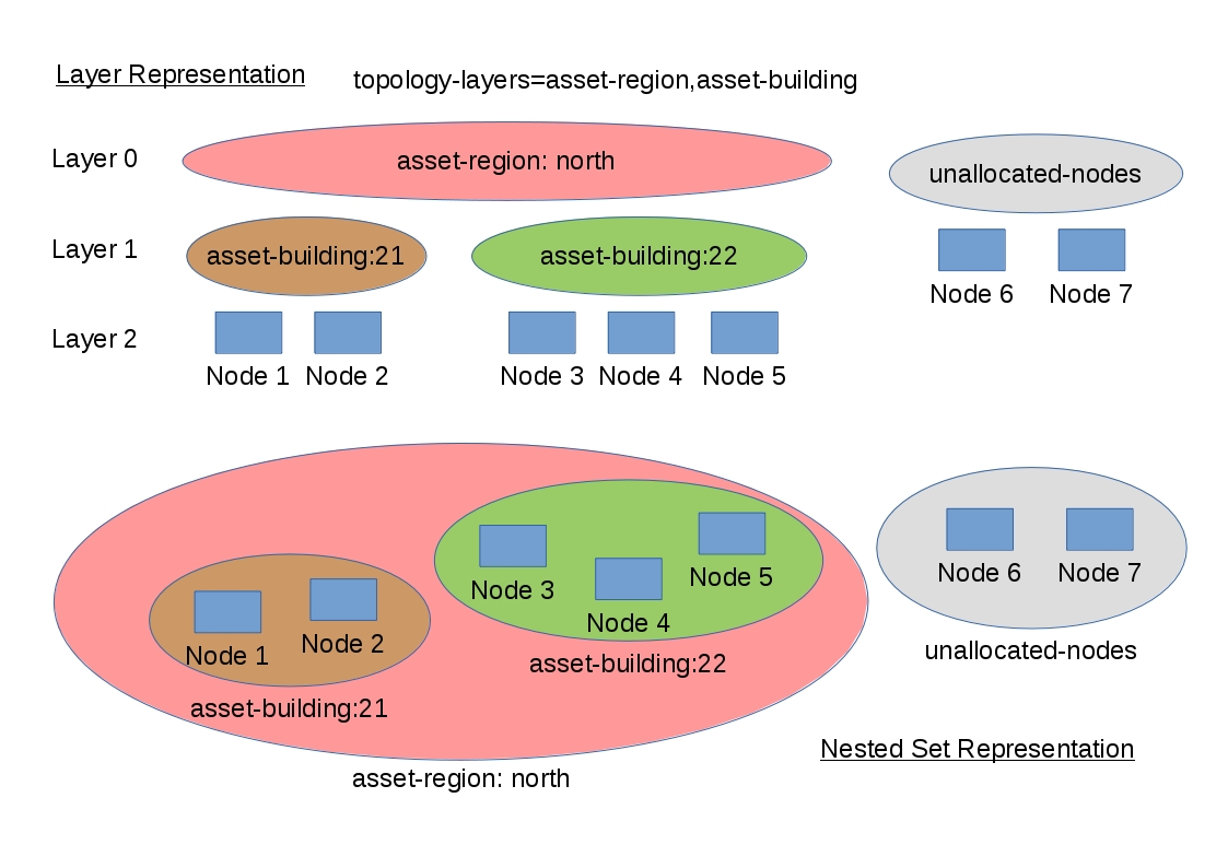
The following diagram shows the structure of a topology generated by the above assetLayers property:

In this example, the region asset fields for nodes 1, 2, 3, 4 are set to north.
All of these nodes are in the same north region.
The building asset fields for node 1 and node 2 are set to 21 (both nodes are in building 21), while the building asset fields for node 3 and node 4 are set to 22 (both nodes are in building 22).
The Asset Topology Provider generates four linked graphs for this configuration.
The layer 0 graph is called asset-region, the layer 1 graph is called asset-building, and the layer 2 graph is called nodes.
Conceptually, the topology is rendered as concentric sets. The Asset Topology Provider first searches all of the nodes with regions defined and creates a new level 0 graph node representing each region found. The Asset Topology Provider then searches within each region to find the building entries and creates a corresponding level 1 graph node for each building name found. Finally, the Asset Topology Provider creates layer 2 nodes corresponding to each Meridian monitored node and places each in the correct building.
Meridian-monitored nodes that have empty region or building asset fields cannot be placed correctly in this topology. These nodes are shown in the diagram as unallocated nodes. Finally, only building and region nodes are generated which can be linked to Meridian nodes in the topology. The Asset Topology Provider does not generate spurious graph nodes in upper layers that are not directly and completely referenced by Meridian nodes in the lowest layer.
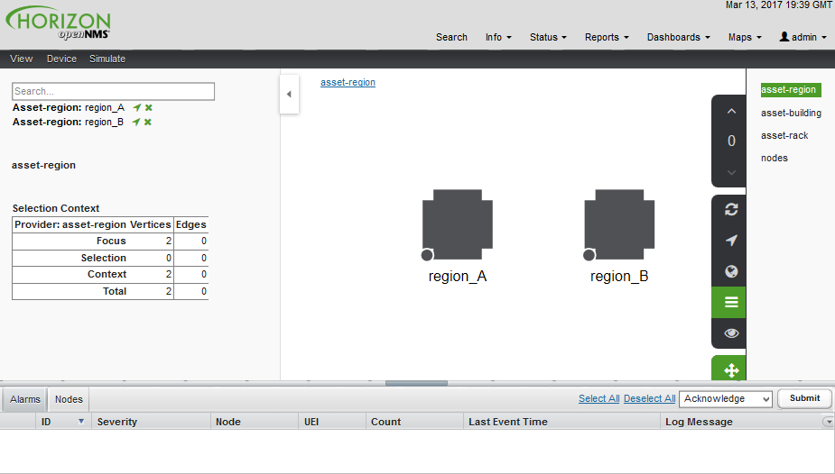
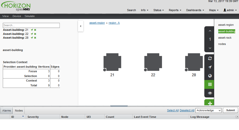
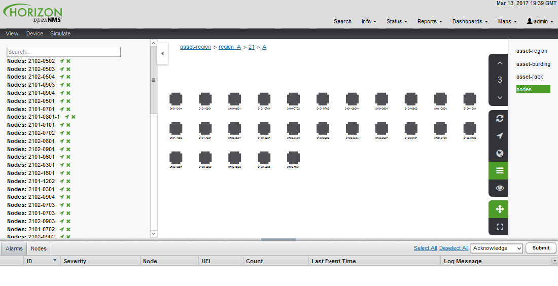
Example screenshots of a topology containing regions, buildings, racks, and nodes:


Asset layers
The entries for assetLayers can be any node or asset entry from the following list (defined in class NodeParamLabels).
Keys beginning with node- come from the node table.
Keys beginning with parent- come from the node table entry of the designated parent node (if defined).
Keys beginning with asset- come from the corresponding asset table entry for the given node (if defined).
Node fields |
||||
node-nodelabel |
node-nodeid |
node-foreignsource |
node-foreignid |
node-nodesysname |
node-nodesyslocation |
node-operatingsystem |
node-categories |
||
Parent node fields |
||||
parent-nodelabel |
parent-nodeid |
parent-foreignsource |
parent-foreignid |
|
Node asset fields |
||||
asset-address1 |
asset-address2 |
asset-city |
asset-zip |
asset-state |
asset-latitude |
asset-longitude |
asset-region |
asset-division |
asset-department |
asset-building |
asset-floor |
asset-room |
asset-rack |
asset-slot |
asset-port |
asset-circuitid |
asset-category |
asset-displaycategory |
asset-notifycategory |
asset-pollercategory |
asset-thresholdcategory |
asset-managedobjecttype |
asset-managedobjectinstance |
asset-manufacturer |
asset-vendor |
asset-modelnumber |
asset-description |
asset-operatingsystem |
asset-country |
This lets you generate arbitrary topologies, including physical fields (room, rack) and logical fields (asset node categories).
Note that you should not put any spaces in the comma-separated assetLayers list.
If the assetLayers property is defined as empty, then a single graph layer is generated containing all OpenNMS nodes.
Node filtering
In many cases, it is desirable to control which nodes are included or excluded from a topology. For instance, it is useful to be able to generate customized topologies for specific customers that include only regions/buildings, and so on, relevant to their filtered node set. To this end, it is possible to define a node filter that chooses which nodes are included in a generated topology.
Define filters using the same asset table keys that are available for the assetLayers field.
| Operation | Definition | Example |
|---|---|---|
OR |
key1=value1,value2 alternatively key1=value1;key1=value2 |
asset-region=north,south |
AND |
key1=val1;key2=val2 |
asset-region=north;asset-building=23 |
NOT |
key1=!val1 |
asset-building=!23 |
Thus, the following configuration means include only nodes with region north or south but exclude all nodes with building 23.
filter=asset-region=north,south;asset-building=!23The filters treat comma-separated key values as an OR search. Thus we can select based on multiple separate node categories.
The following configuration means show routers and servers on all buildings except building 23.
filter=node-categories=routers,servers;asset-building=!23The filters treat all asset table entries as comma-separated variables (csv). This also means that, for instance, asset-displaycategory could also contain several values separated by commas (for example, customer1, customer2, customer3).
| Make sure that asset addresses and other free-format asset text fields do not contain commas if you want an exact match on the whole field. |
Regular expressions are also allowed. Regular expressions start with the ~ character. You can also negate a regular expression by preceding it with !~.
The following example matches against regions "Stuttgart" and "Isengard" and any building name that ends in 4.
filter=asset-region=~.*gar(t|d);asset-building=~.*4Configuration
The Asset Topology Provider persists both the asset topology graph definitions and the generated GraphML graphs. The persisted definitions mean that it is possible to regenerate graphs without reentering the configuration if the asset table changes.
The Asset Topology Provider persists GraphML graphs alongside any other GraphML graphs in the directory.
${OPENNMS_HOME}/etc/graphmlNote that if you use REST or any other means to generate other GraphML graphs, you should ensure that the providerIds and labels are distinct from those the Asset Topology Provider uses.
The asset graph definitions for the Asset Topology Provider are persisted to the following xml configuration file:
${OPENNMS_HOME}/etc/org.opennms.features.topology.plugins.topo.asset.xmlNormally you should not edit this file directly but use the Karaf console or events to define new graphs.
The configuration file contains each of the graph definitions as properties in the form
<?xml version="1.0" encoding="UTF-8" standalone="yes"?>
<configs>
    <config>
        <label>Asset Topology Provider</label>
        <breadcrumb-strategy>SHORTEST_PATH_TO_ROOT</breadcrumb-strategy>
        <provider-id>asset</provider-id>
        <preferred-layout>Grid Layout</preferred-layout>
        <filters>
            <filter>asset-region=South</filter>
        </filters>
        <layers>
            <layer>asset-region</layer>
            <layer>asset-building</layer>
            <layer>asset-rack</layer>
        </layers>
    </config>
</configs>
The following table describes the individual definition parameters:
| Parameter | Description |
|---|---|
providerId |
The unique name of the provider - used as a handle to install and remove the topology. |
label |
The name that shows up on the topology menu (must be unique). |
assetLayers |
List of asset layers (in order). See asset-layers. |
filters |
List of filters to apply. Filters determine the nodes to include in the graph. See node filtering. |
preferredLayout |
Preferred node layout in generated graphs. |
breadcrumbStrategy |
Breadcrumb strategy used to display breadcrumbs above each graph. |
Create asset-based topologies from Karaf console
Use the Meridian Karaf console to control topology generation. To log in, use the admin password.
ssh admin@localhost -p 8101The following commands are available
| Command | Description | Options |
|---|---|---|
opennms:asset-topo-create |
Creates asset topology. |
(Uses the default settings if a particular setting is not included in the command.) If you simply type |
opennms:asset-topo-remove |
Removes asset topology. |
-i, --providerId : Unique providerId of asset topology (Default: asset). |
opennms:asset-topo-list |
Lists all asset topologies installed. |
all : display detailed view including --uriParams string |
opennms:asset-topo-regenerate |
Regenerates the graphs for the given asset topology definition. |
-i, --providerId : Unique providerId of asset topology to regenerate (Default: asset) |
opennms:asset-topo-regenerateall |
Best-effort regeneration of all asset topologies. (If one graph fails, the command tries to complete the rest of the definitions.) |
Create asset-based topologies using Meridian events
The Asset Topology Provider listens for events that trigger the generation and installation or removal of topologies. The Asset Topology Provider events are defined in the file:
${OPENNMS_HOME}/etc/events/GraphMLAssetPluginEvents.xmlThese events use the default parameters if parameters are not supplied.
To create a new topology from the current OpenNMS inventory, use the following:
sudo ./send-event.pl  uei.opennms.plugins/assettopology/create localhost

(or with parameters)
sudo ./send-event.pl  uei.opennms.plugins/assettopology/create localhost  -p 'providerId test' -p 'label test' -p 'assetLayers asset-country,asset-city,asset-building'-->

other sample possible parameters are

-p 'filters asset-displaycategory=!testDisplayCategory'
-p 'preferredLayout Grid Layout'
-p 'breadcrumbStrategy SHORTEST_PATH_TO_ROOT'
To uninstall an asset topology use
(for default topology providerId)
sudo ./send-event.pl  uei.opennms.plugins/assettopology/remove localhost

(or with specific providerId)
sudo ./send-event.pl  uei.opennms.plugins/assettopology/remove localhost -p 'providerId test'
To regenerate an existing asset topology use
(for default topology providerId)
sudo ./send-event.pl  uei.opennms.plugins/assettopology/regenerate localhost

(or with specific providerId)
sudo ./send-event.pl  uei.opennms.plugins/assettopology/regenerate localhost-p 'providerId test'
To regenerate all existing asset topologies use
sudo ./send-event.pl uei.opennms.plugins/assettopology/regenerateall localhostView the topology
After installing the topology and refreshing your screen, you should see a new topology display option in the Meridian topology page. The label field provides the displayed name of this topology.
The label field does not need to be the same as the providerId that the ReST API uses for the installation or removal of a topology. However, the label field must be unique across all installed topologies.
It is possible to have several topologies installed that have been generated using different configurations. You must ensure that the providerId and label field used for each installation command are different.
Additional notes
Note that you must first uninstall an Meridian GraphML topology before installing a new one. You will also have to log out and log back into the UI to see the new topology file. If you uninstall a topology while viewing it, the UI throws an error and you will also have to log out and back in to see the remaining topologies.