GraphML
In Meridian, the GraphMLTopoloyProvider uses GraphML formatted files to visualize graphs.
GraphML is a comprehensive and easy-to-use file format for graphs. It consists of a language core to describe the structural properties of a graph and a flexible extension mechanism to add application-specific data. […] Unlike many other file formats for graphs, GraphML does not use a custom syntax. Instead, it is based on XML and hence ideally suited as a common denominator for all kinds of services generating, archiving, or processing graphs.
Meridian does not support the full feature set of GraphML. The following features are not supported: nested graphs, hyperedges, ports, and extensions. For more information about GraphML refer, to the Official GraphML Documentation.
A basic graph definition using GraphML usually consists of the following GraphML elements:
-
Graph element to describe the graph
-
Key elements to define custom properties, each element in the GraphML document can define as data elements
-
Node and edge elements
-
Data elements to define custom properties, which Meridian will then interpret
A very minimal example is given below:
<?xml version="1.0" encoding="UTF-8"?>
<graphml xmlns="http://graphml.graphdrawing.org/xmlns"
         xmlns:xsi="http://www.w3.org/2001/XMLSchema-instance"
         xsi:schemaLocation="http://graphml.graphdrawing.org/xmlns
     http://graphml.graphdrawing.org/xmlns/1.0/graphml.xsd">
     <!-- key section -->
    <key id="label" for="all" attr.name="label" attr.type="string"></key>
    <key id="namespace" for="graph" attr.name="namespace" attr.type="string"></key>

    <!-- shows up in the menu -->
    <data key="label">Minimalistic GraphML Topology Provider</data> (1)
    <graph id="minicmalistic"> (2)
        <data key="namespace">minimalistic</data> (3)
        <node id="node1"/> (4)
        <node id="node2"/>
        <node id="node3"/>
        <node id="node4"/>
    </graph>
</graphml>| 1 | The optional label of the menu entry. |
| 2 | The graph definition. |
| 3 | Each graph must have a namespace, otherwise Meridian refuses to load the graph. |
| 4 | Node definitions. |
Create/Update/Delete GraphML Topology
To create a GraphML Topology, a valid GraphML xml file must exist. Afterwards this is sent to the Meridian REST API to create it:
curl -X POST -H "Content-Type: application/xml" -u admin:admin -d@graph.xml 'http://localhost:8980/opennms/rest/graphml/topology-name'The topology-name is a unique identifier for the topology.
If a label property is defined for the Graphml element it is displayed in the Topology UI, otherwise the topology-name defined here is used as a fallback.
To delete an already existing Topology send an HTTP DELETE request:
curl -X DELETE -u admin:admin 'http://localhost:8980/opennms/rest/graphml/topology-name'There is no PUT method available. To update an existing GraphML topology one must first delete and afterwards recreate it.
Even if the HTTP request was successful, it does not mean that the topology is actually loaded properly.
The HTTP request states that the graph was successfully received, persisted, and is in a valid GraphML format.
However, the underlying GraphMLTopologyProvider may perform additional checks or encounter problems while parsing the file.
If the topology does not show up, check the karaf.log for any clues about what went wrong.
In addition, it may take a while before you can select the topology from the Topology UI.
|
Supported Attributes
A set of GraphML attributes are supported and interpreted by Meridian while reading the GraphML file. The following table explains the supported attributes and for which GraphML elements they may be used.
The type of the GraphML-Attribute can be either boolean, int, long, float, double, or string. These types are defined like the corresponding types in the Java™-Programming language.
| Property | Required | For element | Type | Default | Description |
|---|---|---|---|---|---|
|
yes |
Graph |
|
- |
The namespace must be unique over all existing topologies. |
|
no |
Graph |
|
- |
A description, shown in the Info Panel. |
|
no |
Graph |
|
|
Defines a preferred layout. |
|
no |
Graph |
|
|
Defines a focus strategy. See Focus Strategies for more information. |
|
no |
Graph |
|
- |
Refers to node IDs in the graph.
Required if |
|
no |
Graph |
|
|
Defines the default SZL. |
|
no |
Graph |
|
- |
Defines which Vertex Status Provider to use, e.g., |
|
no |
Node |
|
|
Defines the icon. See Icons for more information. |
|
no |
Graph, Node |
|
- |
Defines a custom label. If not defined, the |
|
no |
Node |
|
- |
Lets you specify the vertex to an OpenNMS node. |
|
no |
Node |
|
- |
Lets you specify the vertex to an OpenNMS node identified by foreign source and foreign id.
Can be used only in combination with |
|
no |
Node |
|
- |
Lets you specify the vertex to an OpenNMS node identified by foreign source and foreign id.
Use only in combination with |
|
no |
Node, Edge |
|
Defines a custom tooltip. If not defined, the |
|
|
no |
Node |
|
|
Sets the level of the Vertex which is used by certain layout algorithms i.e., |
|
no |
Graph, Node |
|
|
Controls the spacing between the paths drawn for the edges when there are multiple edges connecting two vertices. |
|
no |
GraphML |
|
|
Defines the breadcrumb strategy to use. See Breadcrumbs for more information. |
|
no |
GraphML |
|
|
Defines the ID of the container.
Is required to access the Graph Service REST API.
If none is provided the value is calculated by joining the graph namespaces using a |
Focus Strategies
A focus strategy defines which vertices to add to focus when selecting the topology. The following strategies are available:
-
EMPTY No vertex is added to focus.
-
ALL All vertices are added to focus.
-
FIRST The first vertex is added to focus.
-
SPECIFIC Only vertices that ID match the graph’s property
focus-idsare added to focus.
Icons
With the GraphMLTopoloygProvider it is not possible to change the icon from the Topology UI.
Instead if a custom icon should be used, each node must contain a iconKey property referencing an SVG element.
Vertex Status Provider
The vertex status provider calculates the status of the vertex.
There are multiple implementations available that can be configured for each graph: default, script, and propagate.
If none is specified, there is no status provided at all.
Default Vertex Status Provider
The default status provider calculates the status based on the worst unacknowledged alarm associated with the vertex’s node.
To have a status calculated a (Meridian) node must be associated with the vertex.
To do so, set the GraphML attribute nodeID on the GraphML node accordingly.
Script Vertex Status Provider
The script status provider uses scripts similar to the Edge Status Provider.
Just place Groovy scripts (with file extension .groovy) in the directory ${OPENNMS_HOME}/etc/graphml-vertex-status.
All of the scripts will be evaluated and the most severe status will be used for the vertex in the topology’s visualization.
If the script shouldn’t contribute any status to a vertex just return null.
Edge Status Provider
It is also possible to compute a status for each edge in a given graph.
Just place Groovy scripts (with file extension .groovy) in the directory ${OPENNMS_HOME}/etc/graphml-edge-status.
All of the scripts will be evaluated and the most severe status will be used for the edge in the topology’s visualization.
The following simple Groovy script example will apply a different style and severity if the edge’s associated source node is down.
import org.opennms.netmgt.model.OnmsSeverity;
import org.opennms.features.topology.plugins.topo.graphml.GraphMLEdgeStatus;

if ( sourceNode != null && sourceNode.isDown() ) {
    return new GraphMLEdgeStatus(OnmsSeverity.WARNING, [ 'stroke-dasharray' : '5,5', 'stroke' : 'yellow', 'stroke-width' : '6' ]);
} else {
    return new GraphMLEdgeStatus(OnmsSeverity.NORMAL, []);
}
If the script shouldn’t contribute any status to an edge just return null.
Layers
The GraphMLTopologyProvider can handle GraphML files with multiple graphs. Each graph is represented as a layer in the Topology UI. If a vertex from one graph has an edge pointing to another graph, one can navigate to that layer.
<?xml version="1.0" encoding="UTF-8"?>
<graphml xmlns="http://graphml.graphdrawing.org/xmlns"
         xmlns:xsi="http://www.w3.org/2001/XMLSchema-instance"
         xsi:schemaLocation="http://graphml.graphdrawing.org/xmlns
     http://graphml.graphdrawing.org/xmlns/1.0/graphml.xsd">
    <!-- Key section -->
    <key id="label" for="graphml" attr.name="label" attr.type="string"></key>
    <key id="label" for="graph" attr.name="label" attr.type="string"></key>
    <key id="label" for="node" attr.name="label" attr.type="string"></key>
    <key id="description" for="graph" attr.name="description" attr.type="string"></key>
    <key id="namespace" for="graph" attr.name="namespace" attr.type="string"></key>
    <key id="preferred-layout" for="graph" attr.name="preferred-layout" attr.type="string"></key>
    <key id="focus-strategy" for="graph" attr.name="focus-strategy" attr.type="string"></key>
    <key id="focus-ids" for="graph" attr.name="focus-ids" attr.type="string"></key>
    <key id="semantic-zoom-level" for="graph" attr.name="semantic-zoom-level" attr.type="int"/>

    <!-- Label for Topology Selection menu -->
    <data key="label">Layer Example</data>
    <graph id="regions">
        <data key="namespace">acme:regions</data>
        <data key="label">Regions</data>
        <data key="description">The Regions Layer.</data>
        <data key="preferred-layout">Circle Layout</data>
        <data key="focus-strategy">ALL</data>
        <node id="north">
            <data key="label">North</data>
        </node>
        <node id="west">
            <data key="label">West</data>
        </node>
        <node id="south">
            <data key="label">South</data>
        </node>
        <node id="east">
            <data key="label">East</data>
        </node>
    </graph>
    <graph id="markets">
        <data key="namespace">acme:markets</data>
        <data key="description">The Markets Layer.</data>
        <data key="label">Markets</data>
        <data key="description">The Markets Layer</data>
        <data key="semantic-zoom-level">1</data>
        <data key="focus-strategy">SPECIFIC</data>
        <data key="focus-ids">north.2</data>
        <node id="north.1">
            <data key="label">North 1</data>
        </node>
        <node id="north.2">
            <data key="label">North 2</data>
        </node>
        <node id="north.3">
            <data key="label">North 3</data>
        </node>
        <node id="north.4">
            <data key="label">North 4</data>
        </node>
        <node id="west.1">
            <data key="label">West 1</data>
        </node>
        <node id="west.2">
            <data key="label">West 2</data>
        </node>
        <node id="west.3">
            <data key="label">West 3</data>
        </node>
        <node id="west.4">
            <data key="label">West 4</data>
        </node>
        <node id="south.1">
            <data key="label">South 1</data>
        </node>
        <node id="south.2">
            <data key="label">South 2</data>
        </node>
        <node id="south.3">
            <data key="label">South 3</data>
        </node>
        <node id="south.4">
            <data key="label">South 4</data>
        </node>
        <node id="east.1">
            <data key="label">East 1</data>
        </node>
        <node id="east.2">
            <data key="label">East 2</data>
        </node>
        <node id="east.3">
            <data key="label">East 3</data>
        </node>
        <node id="east.4">
            <data key="label">East 4</data>
        </node>
        <!-- Edges in this layer -->
        <edge id="north.1_north.2" source="north.1" target="north.2"/>
        <edge id="north.2_north.3" source="north.2" target="north.3"/>
        <edge id="north.3_north.4" source="north.3" target="north.4"/>
        <edge id="east.1_east.2" source="east.1" target="east.2"/>
        <edge id="east.2_east.3" source="east.2" target="east.3"/>
        <edge id="east.3_east.4" source="east.3" target="east.4"/>
        <edge id="south.1_south.2" source="south.1" target="south.2"/>
        <edge id="south.2_south.3" source="south.2" target="south.3"/>
        <edge id="south.3_south.4" source="south.3" target="south.4"/>
        <edge id="north.1_north.2" source="north.1" target="north.2"/>
        <edge id="north.2_north.3" source="north.2" target="north.3"/>
        <edge id="north.3_north.4" source="north.3" target="north.4"/>

        <!-- Edges to different layers -->
        <edge id="west_north.1" source="north" target="north.1"/>
        <edge id="north_north.2" source="north" target="north.2"/>
        <edge id="north_north.3" source="north" target="north.3"/>
        <edge id="north_north.4" source="north" target="north.4"/>
        <edge id="south_south.1" source="south" target="south.1"/>
        <edge id="south_south.2" source="south" target="south.2"/>
        <edge id="south_south.3" source="south" target="south.3"/>
        <edge id="south_south.4" source="south" target="south.4"/>
        <edge id="east_east.1" source="east" target="east.1"/>
        <edge id="east_east.2" source="east" target="east.2"/>
        <edge id="east_east.3" source="east" target="east.3"/>
        <edge id="east_east.4" source="east" target="east.4"/>
        <edge id="west_west.1" source="west" target="west.1"/>
        <edge id="west_west.2" source="west" target="west.2"/>
        <edge id="west_west.3" source="west" target="west.3"/>
        <edge id="west_west.4" source="west" target="west.4"/>
    </graph>
</graphml>
Breadcrumbs
When multiple layers are used it is possible to navigate between them (navigate to option from vertex' context menu).
To give the user some orientation, enable breadcrumbs with the breadcrumb-strategy property.
The following strategies are supported:
-
NONE No breadcrumbs are shown.
-
SHORTEST_PATH_TO_ROOT generates breadcrumbs from all visible vertices to the root layer (TopologyProvider). The algorithms assumes a hierarchical graph. Be aware that all vertices MUST share the same root layer, otherwise the algorithm to determine the path to root does not work.
The following figure visualizes a graphml defining multiple layers (see below for the graphml definition).
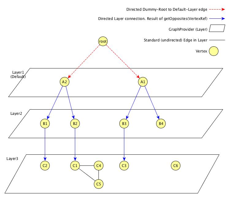
From the given example, the user can select the Breadcrumb Example Topology Provider from the menu.
The user can switch between Layer 1, Layer 2, and Layer 3.
In addition, for each vertex that has connections to another layer, the user can select the navigate to option from the context menu of that vertex to navigate to the appropriate layer.
The user can also search for all vertices and add them to focus.
The following behavior is implemented:
-
If a user navigates from one vertex to a vertex in another layer, the view switches to that layer and adds all vertices to focus, the
source vertexpointed to. The breadcrumb is<parent layer name> > <source vertex>. For example, if a user navigates fromLayer1:A2toLayer2:B1, the view switches toLayer 2and addsB1andB2to focus. In addition,Layer 1 > A2is shown as breadcrumbs. -
If a user directly switches to another layer, the default focus strategy is applied, which may result in multiple vertices with no unique parent. The calculated breadcrumb is:
<parent layer name> > Multiple <target layer name>. For example, if a user switches toLayer 3, all vertices of that layer are added to focus (focus-strategy=ALL). If no unique path to root is found, the following breadcrumb is shown instead:Layer 1 > Multiple Layer 1>Multiple Layer 2 -
If a user adds a vertex to focus that is not in the current selected layer, the view switches to that layer and only the "new" vertex is added to focus. The generated breadcrumb shows the path to root through all layers. For example, if the user adds
C3to focus, and the current layer isLayer 1, then the generated breadcrumb is as follows:Layer 1 > A1 > B3. -
Only elements between layers are shown in the breadcrumb. Connections on the same layer are ignored. For example, if a user adds
C5to focus, the generated breadcrumb is as follows:Layer 1 > A2 > B2
The following graphml file defines the above shown graph. Be aware, that the root vertex shown above is generated to help calculate the path to root. It must not be defined in the graphml document.
<?xml version="1.0" encoding="UTF-8"?>
<graphml xmlns="http://graphml.graphdrawing.org/xmlns"
         xmlns:xsi="http://www.w3.org/2001/XMLSchema-instance"
         xsi:schemaLocation="http://graphml.graphdrawing.org/xmlns
     http://graphml.graphdrawing.org/xmlns/1.0/graphml.xsd">
    <key id="breadcrumb-strategy" for="graphml" attr.name="breadcrumb-strategy" attr.type="string"></key>
    <key id="label" for="all" attr.name="label" attr.type="string"></key>
    <key id="description" for="graph" attr.name="description" attr.type="string"></key>
    <key id="namespace" for="graph" attr.name="namespace" attr.type="string"></key>
    <key id="focus-strategy" for="graph" attr.name="focus-strategy" attr.type="string"></key>
    <key id="focus-ids" for="graph" attr.name="focus-ids" attr.type="string"></key>
    <key id="preferred-layout" for="graph" attr.name="preferred-layout" attr.type="string"></key>
    <key id="semantic-zoom-level" for="graph" attr.name="semantic-zoom-level" attr.type="int"/>
    <data key="label">Breadcrumb Example</data>
    <data key="breadcrumb-strategy">SHORTEST_PATH_TO_ROOT</data>
    <graph id="L1">
        <data key="label">Layer 1</data>
        <data key="namespace">acme:layer1</data>
        <data key="focus-strategy">ALL</data>
        <data key="preferred-layout">Circle Layout</data>
        <node id="a1">
            <data key="label">A1</data>
        </node>
        <node id="a2">
            <data key="label">A2</data>
        </node>
        <edge id="a1_b3" source="a1" target="b3"/>
        <edge id="a1_b4" source="a1" target="b4"/>
        <edge id="a2_b1" source="a2" target="b1"/>
        <edge id="a2_b2" source="a2" target="b2"/>
    </graph>
    <graph id="L2">
        <data key="label">Layer 2</data>
        <data key="focus-strategy">ALL</data>
        <data key="namespace">acme:layer2</data>
        <data key="preferred-layout">Circle Layout</data>
        <data key="semantic-zoom-level">0</data>
        <node id="b1">
            <data key="label">B1</data>
        </node>
        <node id="b2">
            <data key="label">B2</data>
        </node>
        <node id="b3">
            <data key="label">B3</data>
        </node>
        <node id="b4">
            <data key="label">B4</data>
        </node>
        <edge id="b1_c2" source="b1" target="c2"/>
        <edge id="b2_c1" source="b2" target="c1"/>
        <edge id="b3_c3" source="b3" target="c3"/>
    </graph>
    <graph id="Layer 3">
        <data key="label">Layer 3</data>
        <data key="focus-strategy">ALL</data>
        <data key="description">Layer 3</data>
        <data key="namespace">acme:layer3</data>
        <data key="preferred-layout">Grid Layout</data>
        <data key="semantic-zoom-level">1</data>
        <node id="c1">
            <data key="label">C1</data>
        </node>
        <node id="c2">
            <data key="label">C2</data>
        </node>
        <node id="c3">
            <data key="label">C3</data>
        </node>
        <node id="c4">
            <data key="label">C4</data>
        </node>
        <node id="c5">
            <data key="label">C5</data>
        </node>
        <node id="c6">
            <data key="label">C6</data>
        </node>
        <edge id="c1_c4" source="c1" target="c4"/>
        <edge id="c1_c5" source="c1" target="c5"/>
        <edge id="c4_c5" source="c4" target="c5"/>
    </graph>
</graphml>